How to Draw Floor Plan Section Mark in Elevation Revit
Role Two. Revit
Affiliate sixteen. Add/edit meridian, section, detail, text, note, & rooms
Upon completing this session, students volition exist able to:
- (CO i) Add together/Edit Elevations & Sections – Adjust ingather region
- (CO ii) Add together/Edit Detail views
- (CO 3) Add Texts & Annotations
- (CO 4) Add/Edit Rooms, Room tags, Room separators
- (CO 5) Add/Edit a color fill scheme
 Session Highlights
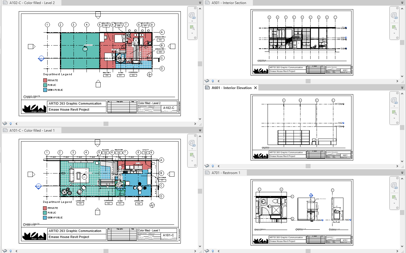
At the end of the session, students can create the graphics below.
 Lecture Contents
(CO one) Add/Edit Elevations & Sections – Adjust crop region
Y'all can create sections or elevations in any floor plans.
To add an interior elevation
- [Footstep one] Open up the projection, and open [Level one] floor program
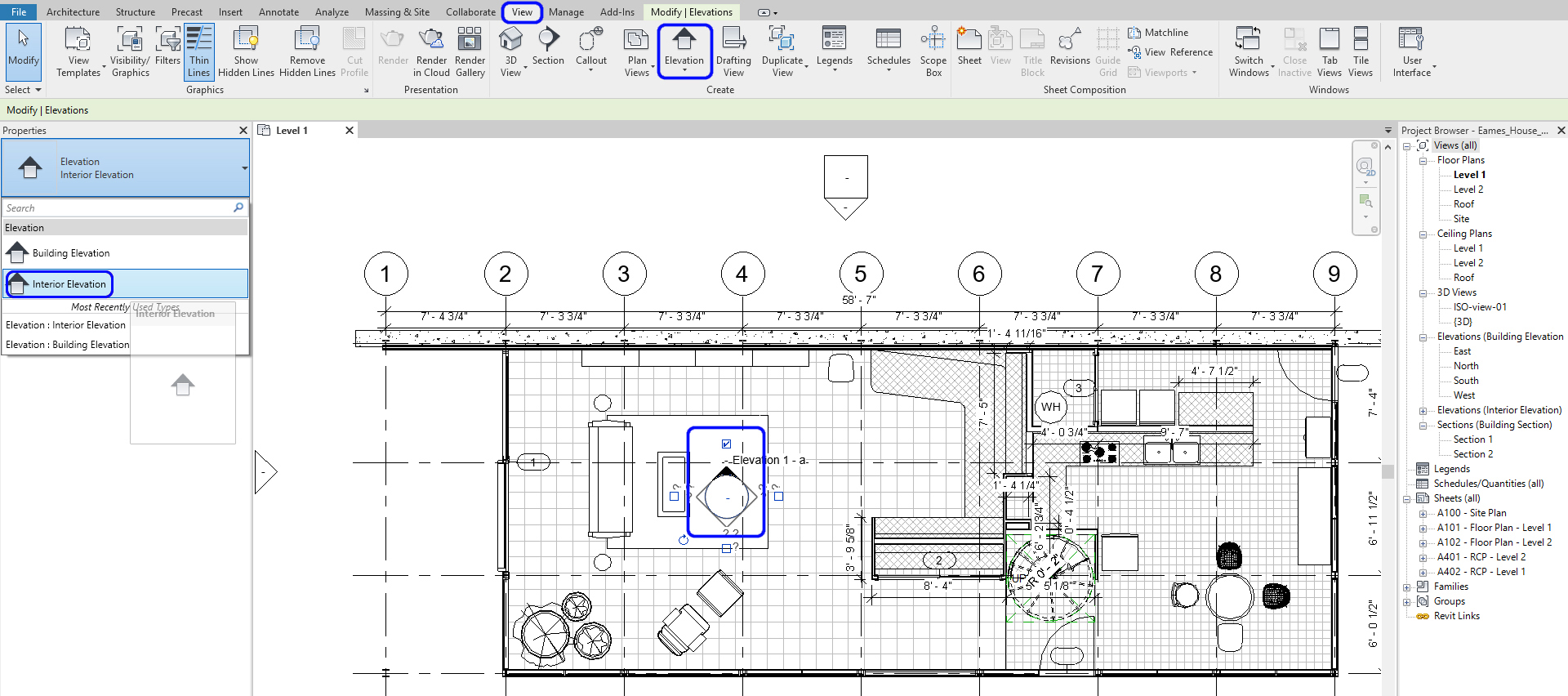
- [Stride two] Click [Elevation] from [View] tab, under [Create] console
- [Step iii] Click the [Backdrop] palette > select Interior Elevation, the symbol volition exist updated.
- [Pace 4] Hover over your plan. You will discover the acme marker will "snap" parallel to walls. Please select the location where you want to place your elevation and click to set information technology in identify. Press [Esc] to complete the control
- [STEP five] Select the elevation tag. Yous can create boosted elevations from ane peak symbol. Printing [Esc] to complete the command
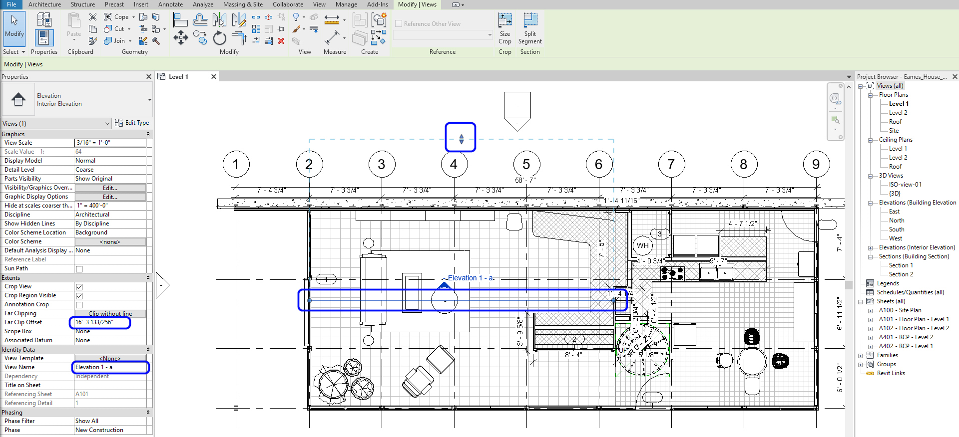
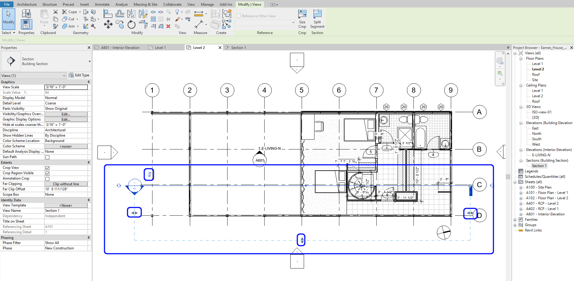
- [STEP 6] Select the elevation arrow (black filled) to adjust the crop region and view depth past moving the blue line; you tin adjust where the pinnacle view begins. By adjusting the blue nodes on the line, you can define the crop region. Moreover, by moving the arrows, you can adjust the view depth of the elevation.
- [STEP 7] Once your elevation is divers, double click on the arrow of the peak symbol > the newly created pinnacle view will be open. Yous may realize the current view is not what you want to nowadays. If the view shows right, delight skip [STEP 8] and [Stride 9]
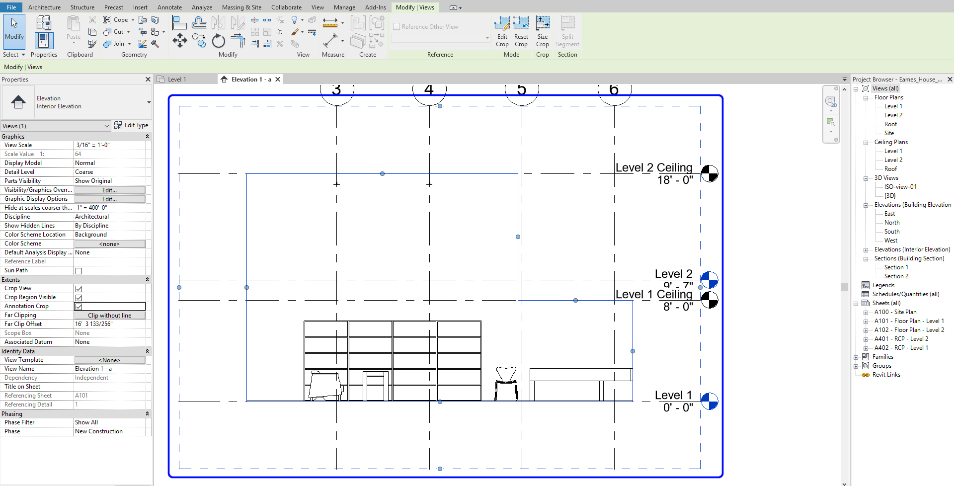
- [Pace 8]Click the border of the meridian > click [Edit Ingather]
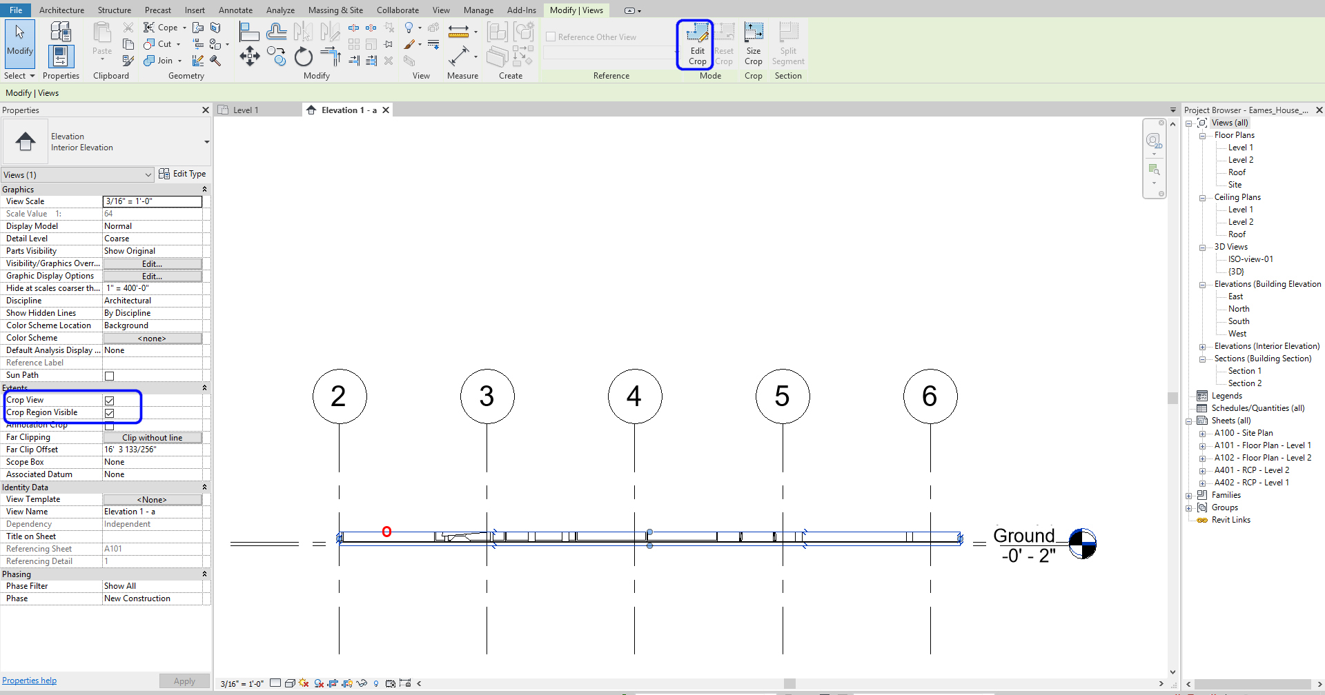
- [Stride 9] Redraw the boundary of the elevation. The boundary must be a closed-loop > Click [Green check-mark] to finish the crop boundary.
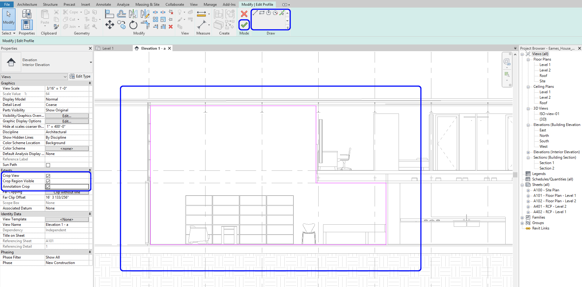
- [STEP 10] Make sure you check all three [Crop view], [Crop Region Visible], and [Annotation Crop] on [Backdrop] palette.
Note. The solid blueish defines the visible region, and the dashed line defines where your annotations can be viewed and placed. Additionally, you can continue to arrange their view ranges past clicking on the nodes.
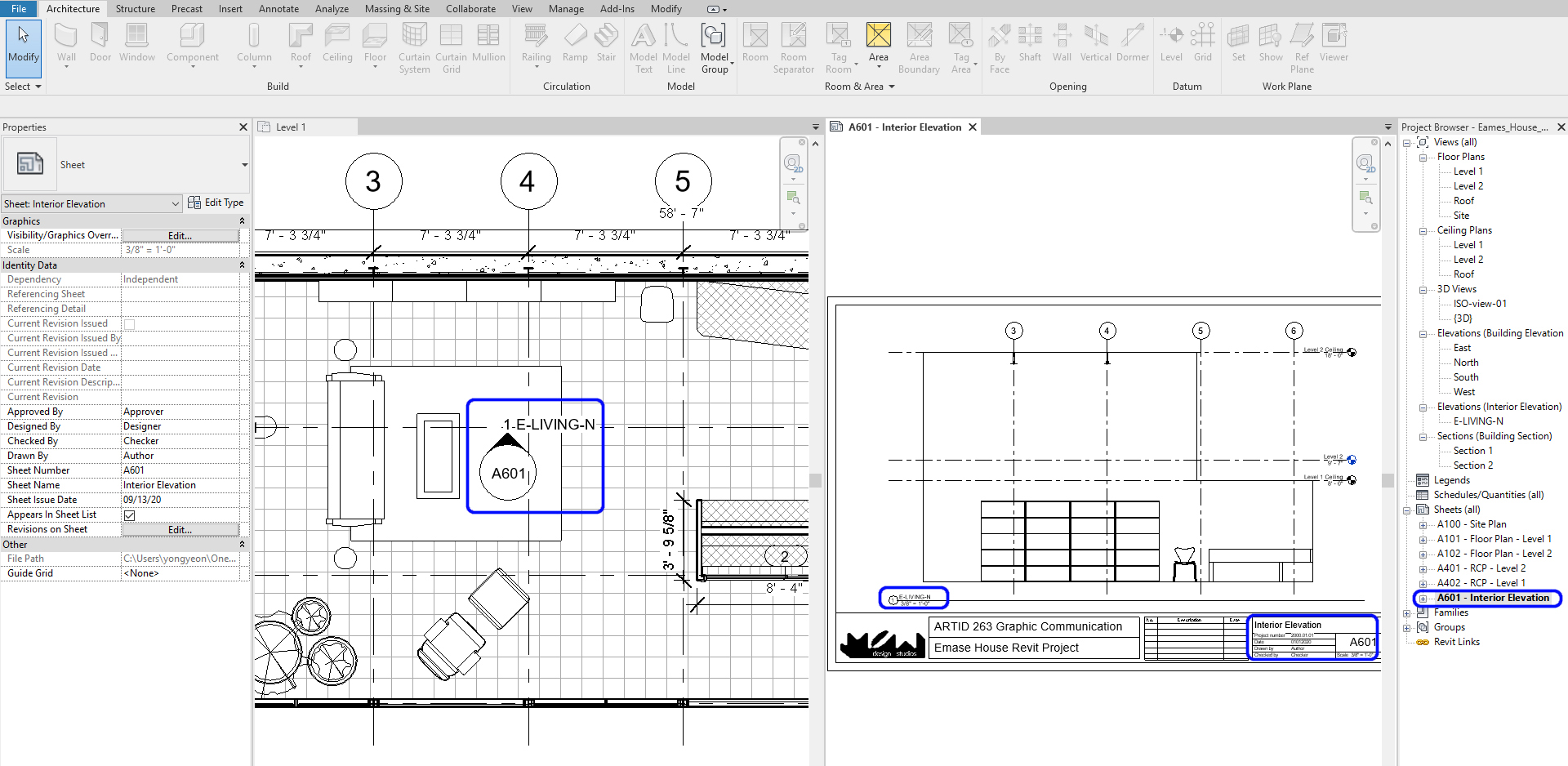
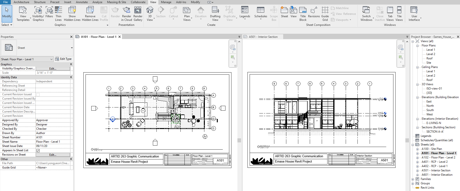
- [Step 11] Add a sheet for the elevation past mouse correct-clicking and clicking [New Sail] on Sheets(all) from [Project Browser] > Select 11×17 titleblock page that you created > Rename the sheet – Sheet number [A601], Sail name – Interior Acme > Once the empty sheet is open > Drag the tiptop view from [Project Browser] to the sheet > Rename the view title [E-LIVING-Northward] > And so you can see the elevation symbol name and view name updated on the floor plan
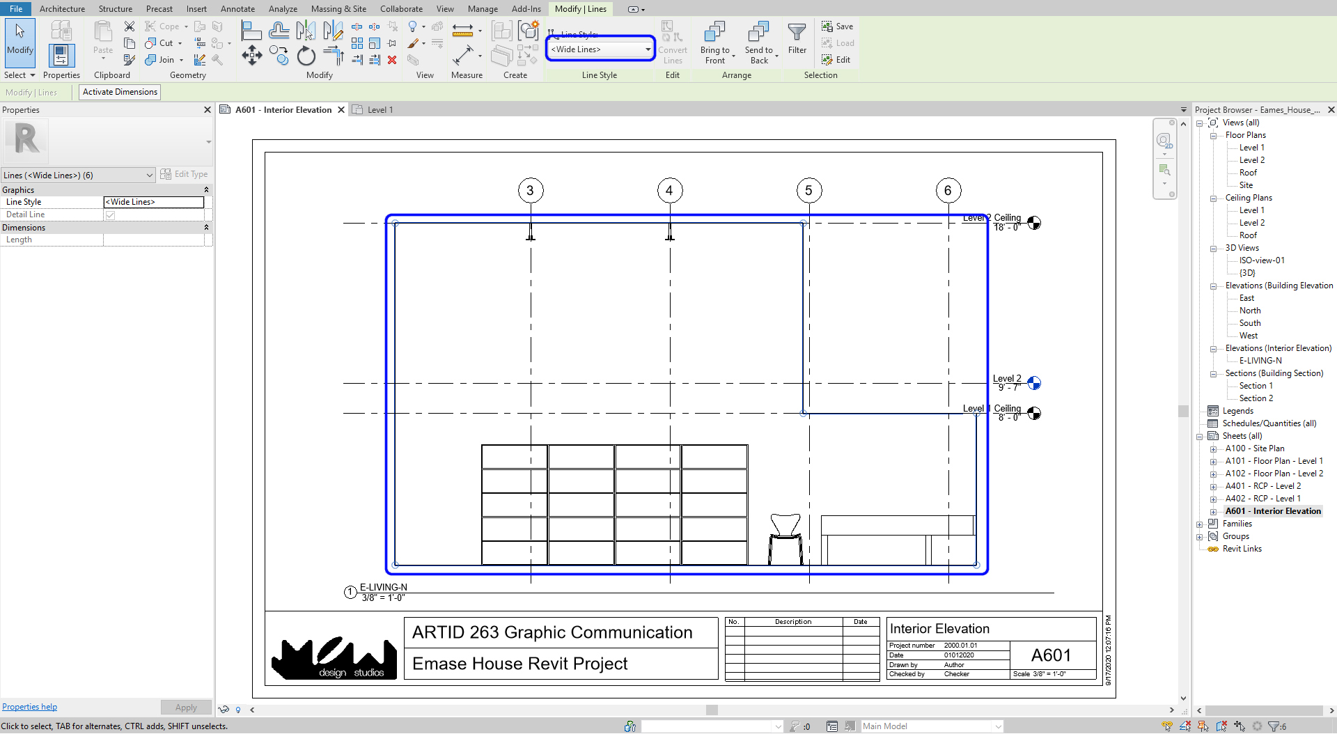
- [STEP 12] Usually, we want to show the boundary of top in a bold line. On your sheet, add [Item Line] from [Annotation] tab, under [Item] panel, or type [DL] > Select [Wide Lines] from [Change] tab, nether [Line Styles] > Trace the boundary lines
To add together a section view
- [STEP 1] Y'all will apply similar steps to create department views
- [STEP ii] Click [Department] from [View] tab, under [Create] panel
- [Stride 3] Describe a section line by clicking two points, then you can modify the view direction and boundary of the view
- [STEP 4] Set a sheet for the department
(CO 2) Add/Edit Detail views
Add detailed views
- [Footstep i] Click [Callout] from [View] tab, under [Create] panel
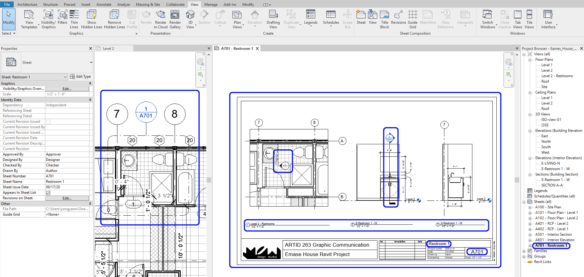
- [STEP 2] Draw the boundary of a view on your floor plan > then [Level 2-Callout] will be automatically created under [Floor plans] > Rename the view to [Level 2 – Restrooms] > If needed, update the scale
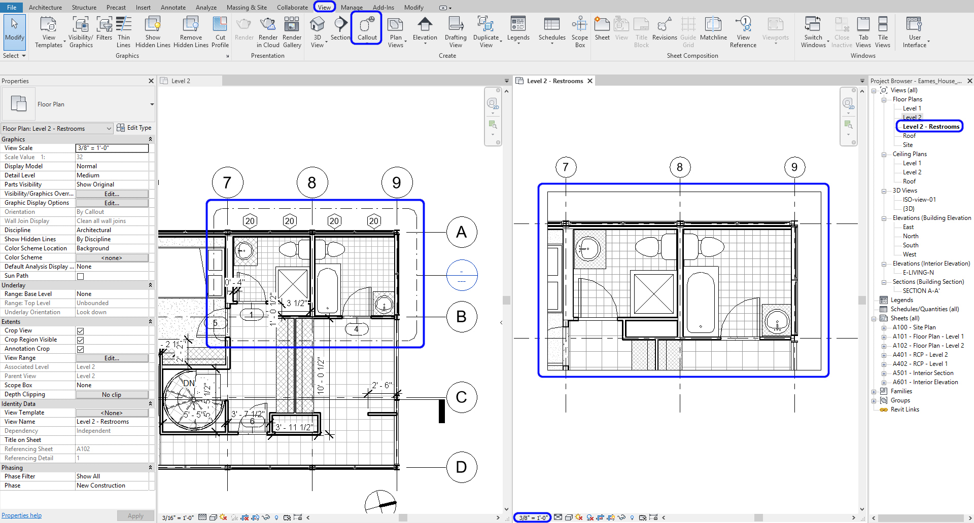
- [STEP 3] Create an acme view and a department view on the item view > add details > Update scales > Hide [meridian symbol] on [Level 2] floor program > Hide [Section symbol] on [Level 2 – Restrooms] item view and [Level 2] floor plan
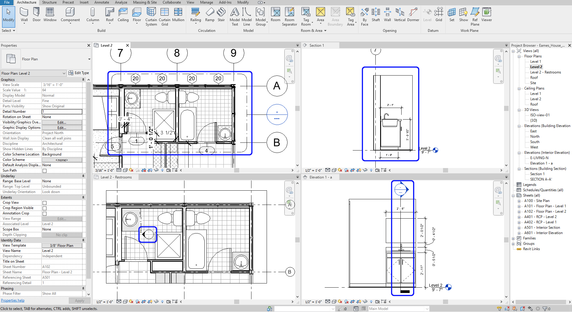
- [Stride 4] Add together the item views to the canvas [A701-Restroom 1]
(CO iii) Add Texts & Annotations
Annotation (Texts, Notes, and Dimensions) can exist added to any views and sheets
In this tutorial, y'all volition practice the [TEXT] tool to add texts and notes
- [STEP 1] Open a [view] from [canvass] by double-clicking the view > On the view, click [Text] from [Annotate] tab, under [Text] panel > Select a text type from [Properties] panel > Drag and drop to make a text box > Add text
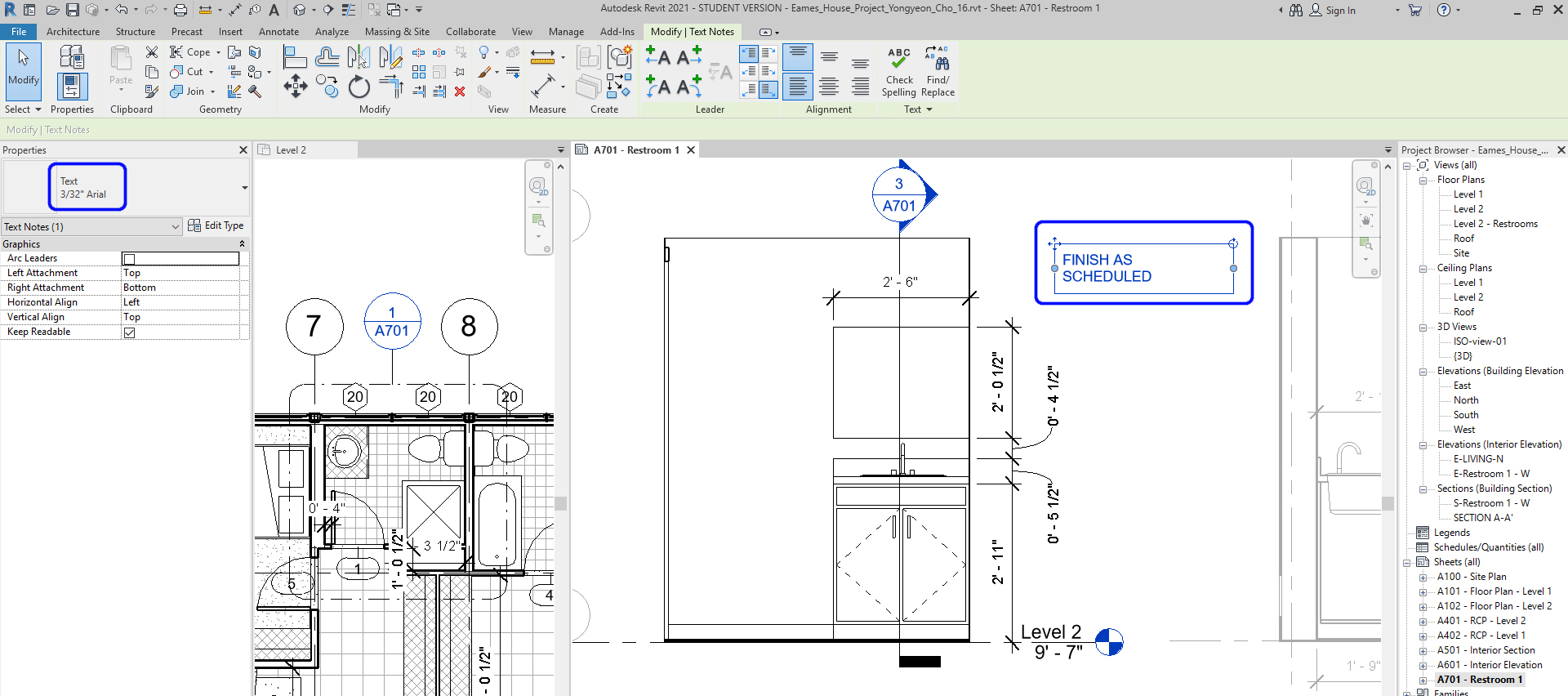
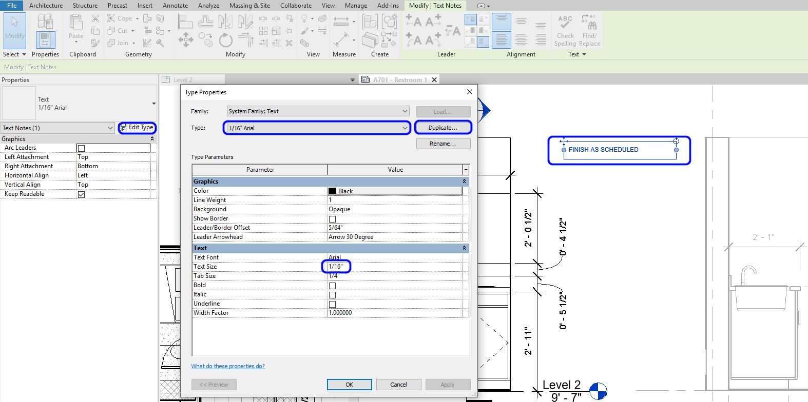
Notation. If you demand a different style of text type, you can indistinguishable the type and edit
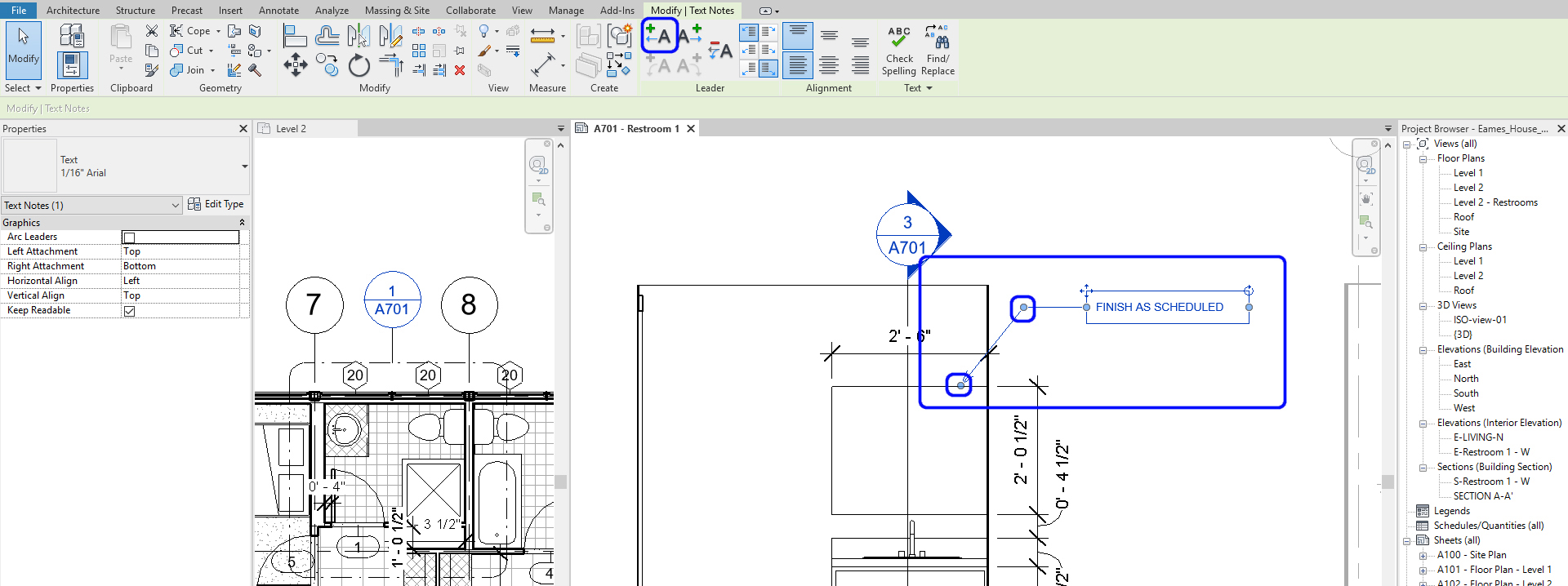
- [STEP 2] Add together a leader line(south) by clicking the [Leader] icon from the [Change] tab > accommodate pointer direction and the leader line
(CO 4) Add together/Edit Rooms, Room tags, Room separators
Some other useful annotation tool is creating, defining, and tagging rooms in Revit. Once you have walls, Revit recognizes the walls every bit the boundary of the rooms. Notwithstanding, if yous have unclear boundaries, you have to ascertain room boundary past using [Room Separator] outset
Ostend room boundaries
- [STEP i] Click [Room] from [Architecture] tab, under [Room & Area] panel
- [Footstep two] Hover the mouse over the floor plan to discover a closed room. Y'all can ostend the boundaries by clicking [Highlight Boundaries]
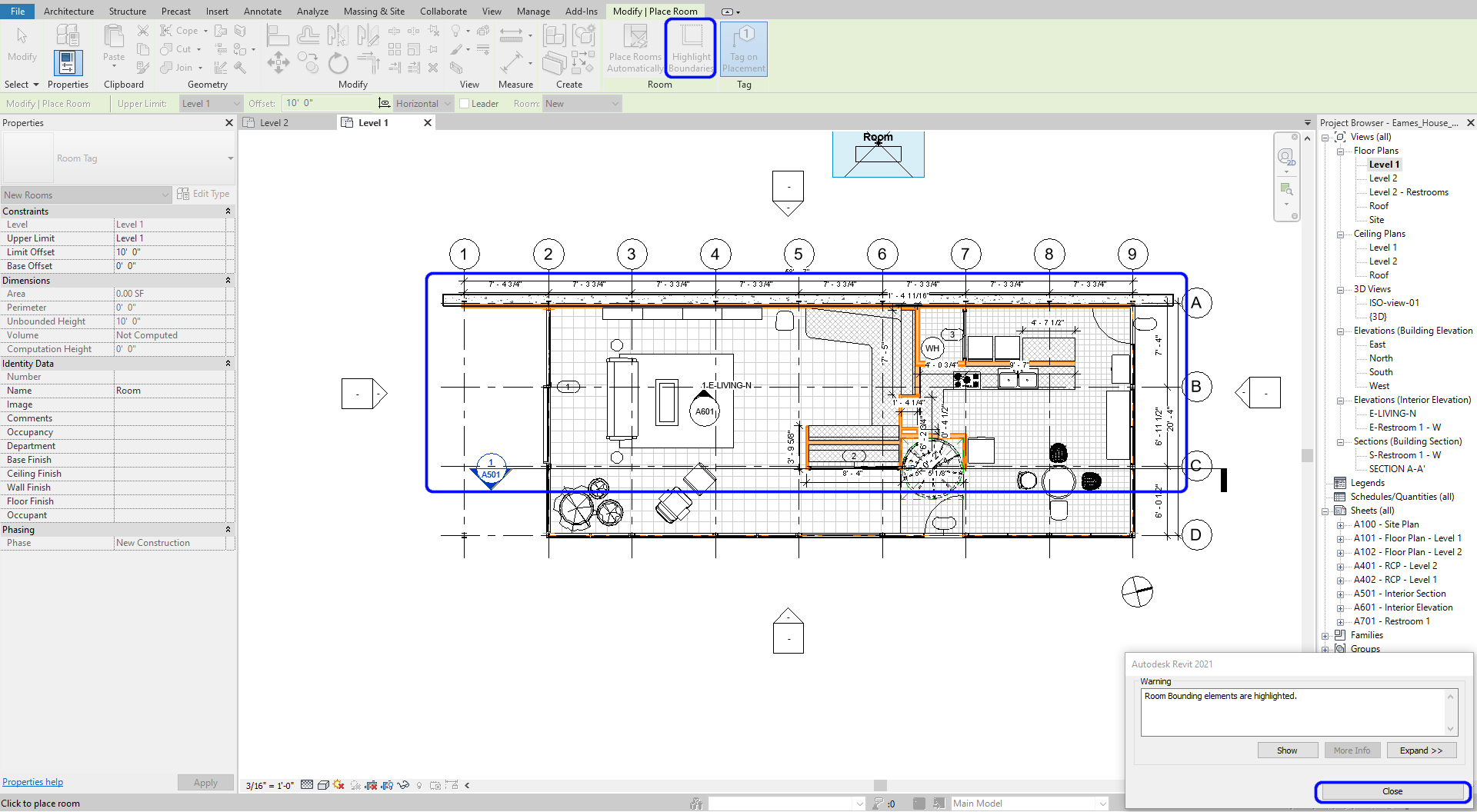
- [STEP iii] Click [Close] to hibernate the highlighted boundaries
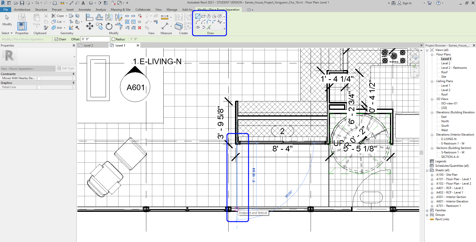
Define boundaries
- [STEP 1] To define boundaries, click [Room Separator] from [Compages] tab, nether [Room & Area] panel
- [STEP 2] Using [Depict] tool to describe separated boundaries, then you can manually define boundaries.
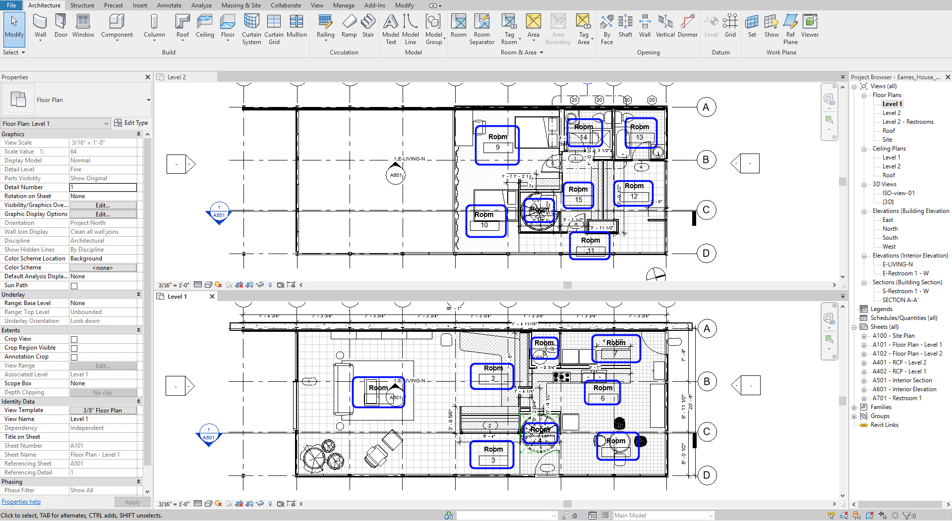
Create rooms
- [Pace 1] Click [Room] from [Architecture] tab, under [Room & Area] console
- [Stride ii] Hover over each room and click in one case with the mouse to ascertain the room boundary. You will encounter a tag that reads [ROOM] and a [X] showing the extent of the room. Continue for each room.
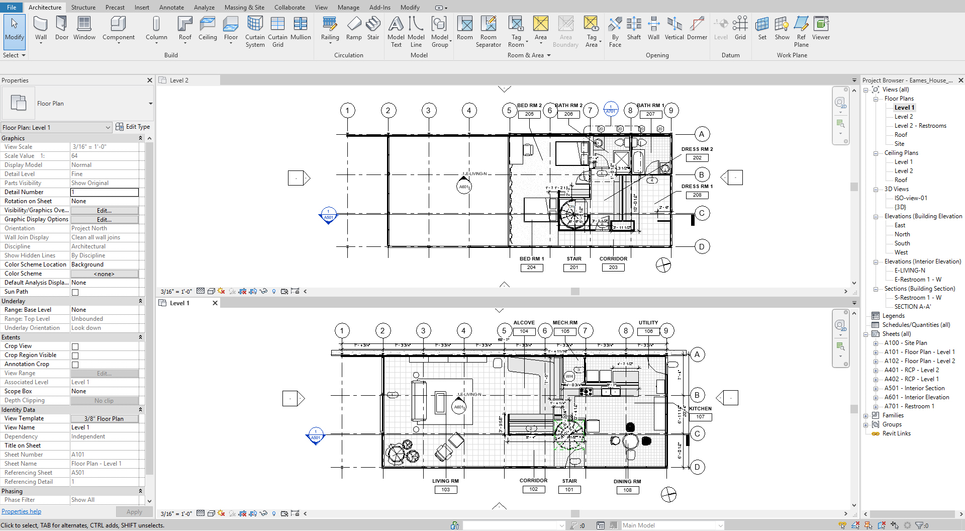
Edit tags
- [STEP one] Click a room tag (Name) two times, then y'all can edit the room proper name. Click a room tag (NUMBER) two times. And then you tin edit the room number.
Note. If the rooms are located on the 1st floor, the number starts from 101. If the rooms are located on the 2nd floor, the number starts from 201. - [STEP 2] Motion the room tags exterior of the room to avoid overlapping with model lines and the room names > Select all room tags > Check [Leader Line] box > Motility the room tags to the outside of the room
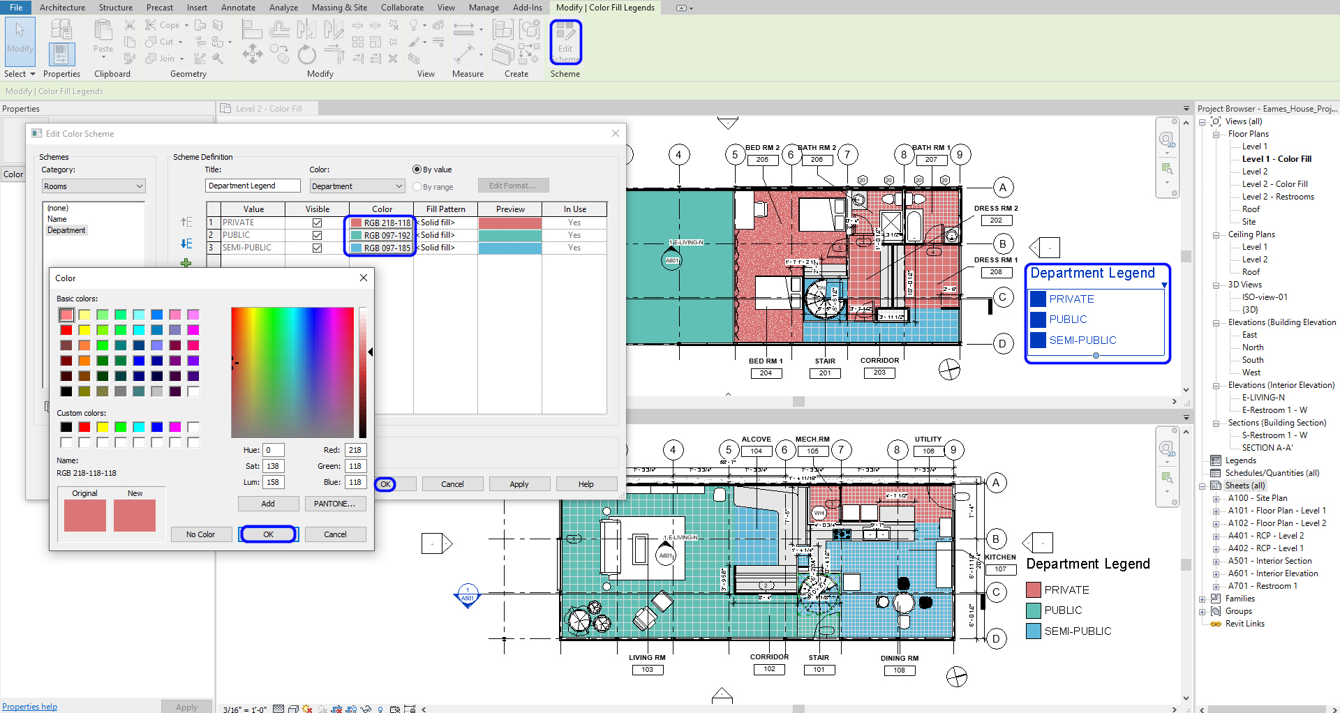
(CO 5) Add together/Edit a color fill scheme
You can use the [colour fill up legend] to place rooms and spaces after calculation rooms. Colour coding plans tin can help the client sympathise the relationship between public and private, work, and rest spaces.
Add a color fill up legend
- [Pace 1] Click a [room] on a floor plan > Add [PUBLIC], [SEMI-Individual], or [PRIVATE] on [Department] from [Properties] palette > If you already added one of the three options, y'all tin select from the driblet-down carte.
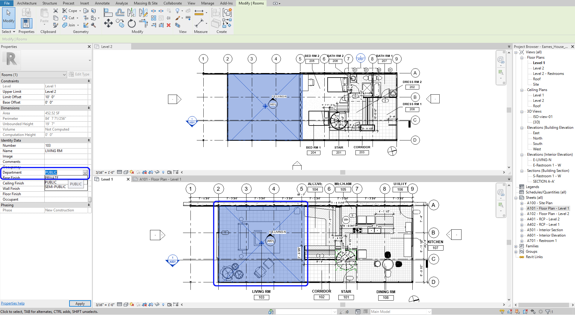
- [Footstep ii] Repeat step ane for all rooms
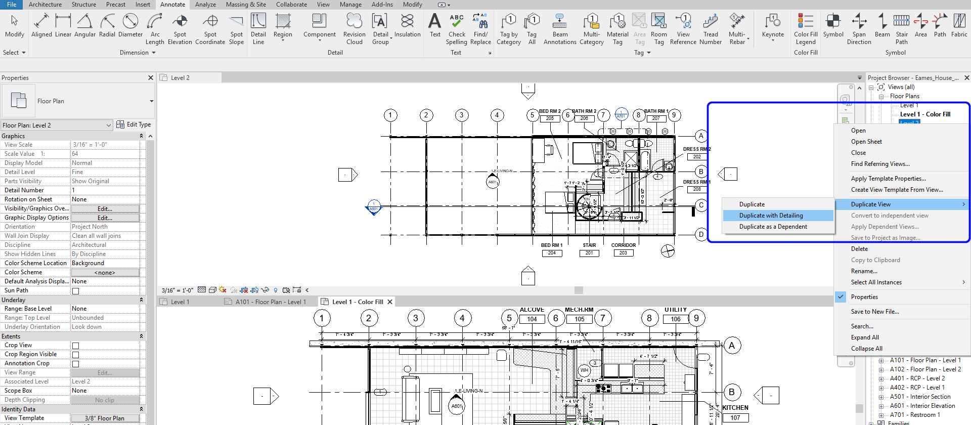
- [STEP iii] Indistinguishable floor plans for but the color-filled plans by right-clicking a view > select [Duplicate view] > select [Duplicate with Detailing] > Rename the copied views
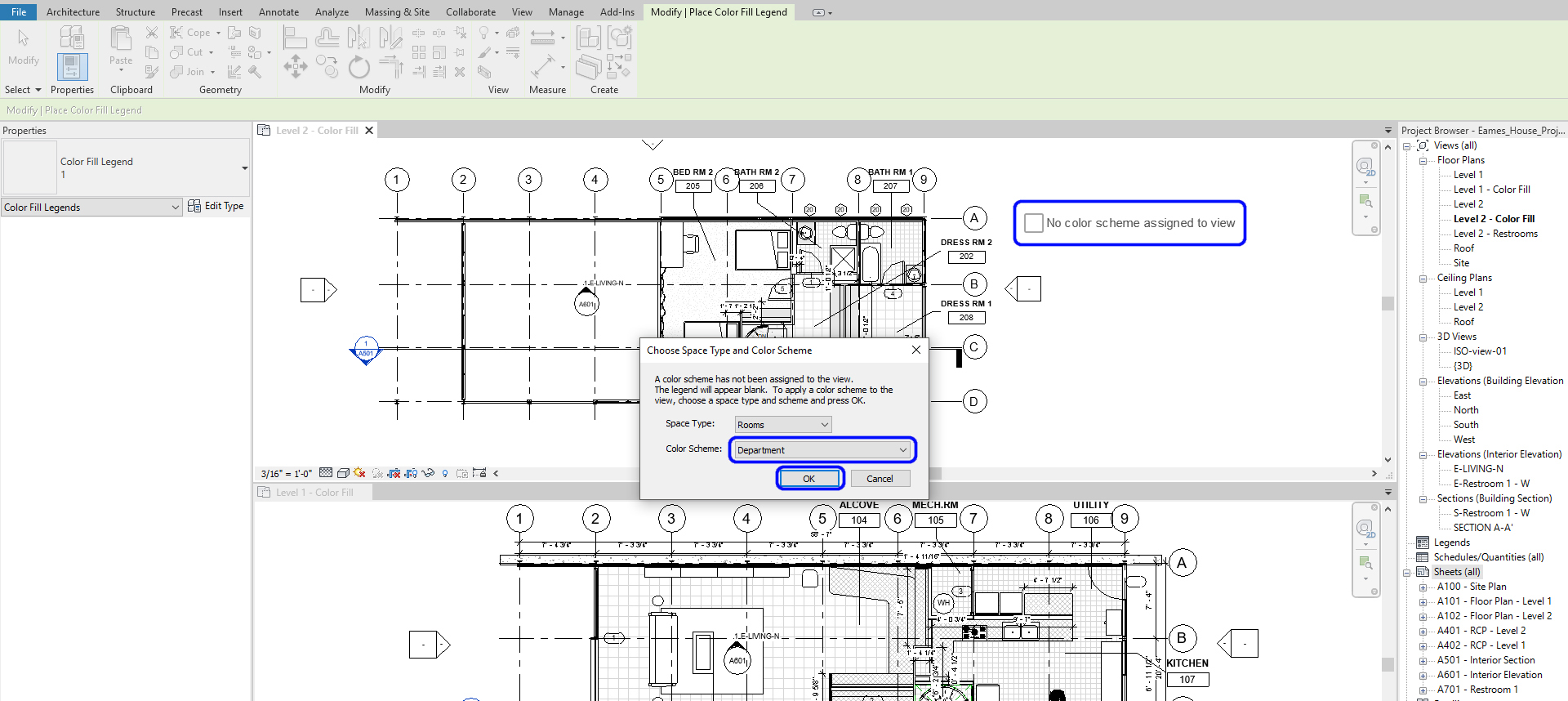
- [Step iv] Open the duplicated views > Click [Color Fill Legend] from [Annotate] tab, under [Color Fill up] panel > Click on a floor plan, so [Choose Space Type and Color Scheme] window will open > Ostend Infinite type: Room, Color Scheme: Department > Click [OK] so the color-filled legend and colour volition prove.
- [STEP 5] Repeat this step 4 for another programme
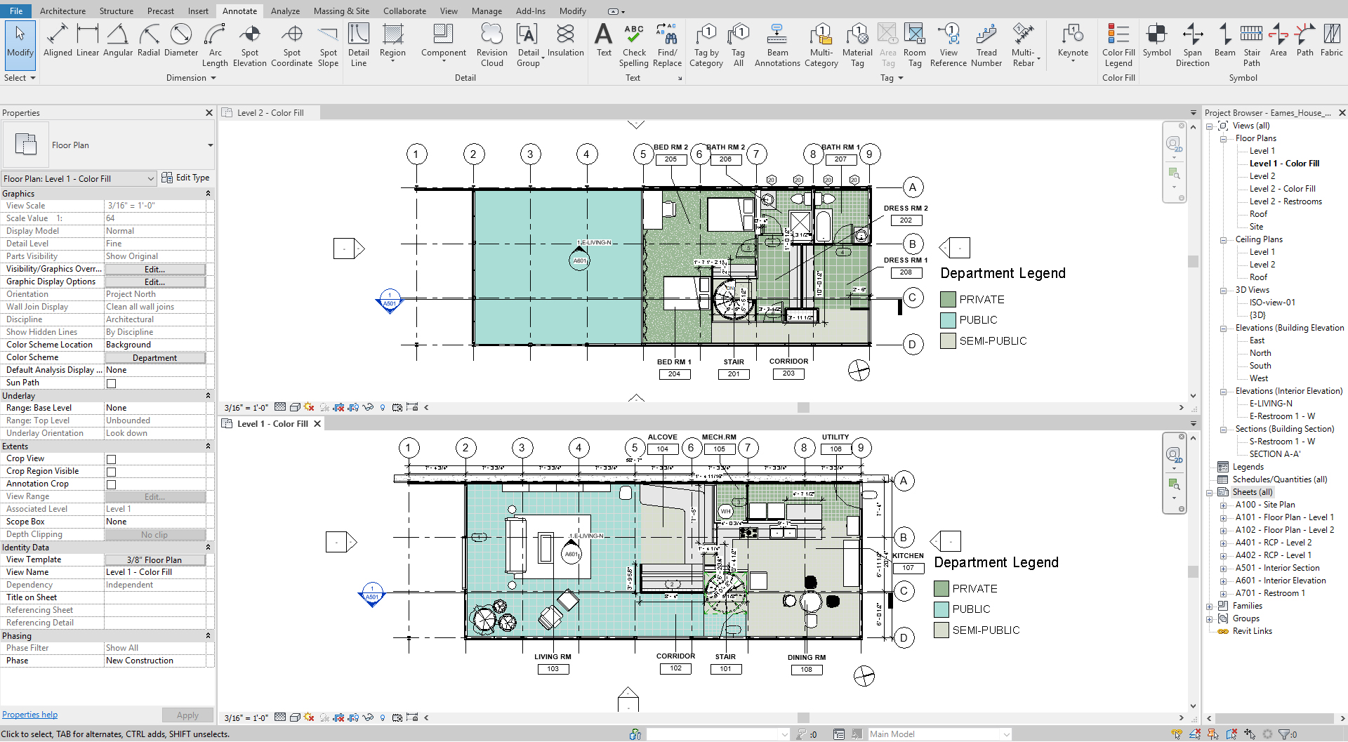
- [STEP half dozen] To update color, Click the legend > click [Edit Scheme] > Ascertain colour> Click [OK] to finish color scheme
Relieve the file before closing the awarding.
Save in a different location for the fill-in (e.g., a deject folder)
Source: https://iastate.pressbooks.pub/visualgraphiccomm/chapter/chapter-16-add-edit-elevation-section-detail-text-annotation-room/
Belum ada Komentar untuk "How to Draw Floor Plan Section Mark in Elevation Revit"
Posting Komentar